Table Of Content
We always set realistic deadlines when preparing the spec and stick to the schedule at all project stages. I believe this has sparked enough interest to start with our tutorial series. In the next part we will learn more about schematics editor and how to use in to create your own schematics on Eagle. Modify the dimensions of the outline box by using the MOVE command on the corners or by right-clicking on a segment.
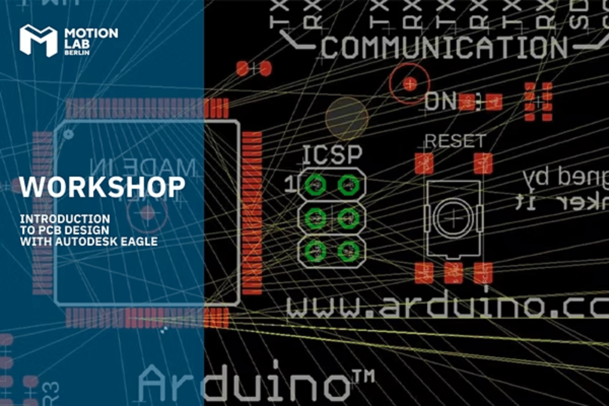
How to Implement PCB Design Step by Step Using Eagle
Make sure you click on the very end of the pin when you start or finish a net route. If you need to move parts around, use the MOVE tool -- (left toolbar or under the Edit menu). Left-click once on a part to pick it up (your mouse should be hovering over the part's red "+" origin). Then left click again when it's where it needs to be.
Routing the Signals
Creating the board from a schematic is one of the easiest tasks with EAGLE. Click the Board icon and EAGLE opens a new window with all the parts arranged next to a default board outline. All the nets from the schematic are shown as air wires. In the intricate world of electronics, every detail in your PCB layout matters. At 911EDA, we understand the nuances that transform a good design into an exceptional one.
Arranging the Board
Don't Get Zapped! What to Know About ESD EAGLE Blog - Autodesk Redshift
Don't Get Zapped! What to Know About ESD EAGLE Blog.
Posted: Mon, 31 Jul 2017 07:00:00 GMT [source]
Change this to 'Gerber RS-274X' and then press process job. As shown in the short video above, they help organize and keep circuits as compact and efficient as possible. Designing and manufacturing your own might seem like a daunting task, but please do not worry. After you feel like the routing is done, there are a few checks we can do to make sure it's 100% complete. Below is an example of how you might lay out your board while considering those factors. We've minimized airwire intersections by cleverly placing the LEDs and their current-limiting resistors.
SparkFun Snappable Protoboard
With the NAME tool selected, clicking on a net should open a new dialog. Start by naming the net connected to the top, GND pin. Delete the auto-generated name (e.g. N$14), and replace it with "GND" (sans the quotation marks).
Much later, in 2015, a special version of EAGLE 4.09r2 was made available by CadSoft to ease installation under Windows 7. Use SparkFun's CAM files, to create Gerber files that are accepted by most fab houses. Designing a schematic is the first step in PCB design. A well-designed schematic is critical to the whole process. Scripts are a much more streamlined way to quickly configure your interface. With one click of the button, you can automatically set up all of your colors and key binds.
The Move command allows you to pick up each part and move it to its desired position. The right mouse button rotates the current part or group. The middle mouse button mirrors a part onto the bottom side of the board. Partner with us, where the designer includes a commitment to quality and innovation, from concept to production. Choose 911EDA for our unparalleled expertise in high-speed PCB design, including rigid-flex PCB design specialists. We are committed to providing cost-effective solutions, ranging from simple layouts to complex aerospace PCB designs, with quick turnarounds that meet your project deadlines.
Copper pours are usually a great addition to a board. They look professional and they actually have a good reason for existing. Usually, when you're adding a copper pour it's for the ground signal. If ratsnest says you have "N airwires" left to route, double check your board for any floating golden lines and route them up. If you've looked all over, and can't find the suspect airwire, try turning off every layer except 19 Unrouted. The new board file should show all of the parts from your schematic.
Tutorial 1/4 - Getting Started with EAGLE for PCB Designing
After placing a part, the add tool will assume you want to add another -- a new frame should start following your cursor. To get out of the add-mode either hit escape (ESC) twice or just select a different tool. Give the newly created, red project folder a descriptive name. It can be hard to tell what is and isn't connected to the ground pour.
Learn how to successfully migrate your design and library files from Autodesk EAGLE to Autodesk Fusion with a simple, four-step guide. The timing of a project largely depends on its specifics, complexity, scale, choice of components, and logistics. For example, a project audit can take 1-2 months, while AI-based software development usually lasts much longer.
To begin the design process, we need to lay out a schematic. The tabs in this view (Layers, Clearance, Distance, etc.) help define a huge set of design rules which your layout needs to pass. These rules define things like minimum clearance distances, or trace widths, or drill hole sizes...all sorts of fun stuff. Instead of setting each of those manually, you can load up a set of design rules using a DRU file. And select the SparkFun.dru file you just downloaded. The title of the window will change to "DRC (SparkFun)", and some values on the other tabs will change.


No comments:
Post a Comment